


Here's what I encountered as I removed my Quadra-Trac (QT) transfer case to fix the transmission input seal.
Note that disassembly of the transfer case is NOT required to replace the transmission input seal, actually called the (transmission) output shaft seal in the TSM (Technical Service Manual). Since my QT unit had been bathed in a mixture of QT fluid and Dexron (transmission fluid) due to the failed seals, I decided to tear it down and clean out the insides.
The usual disclaimers apply. Don't blame me if you drop the transfer case on your head or if the case blows up on the side of a mountain and you have to replace it lying on your back in
you how I did it. With that out of the way, let's get started.
Of course, I followed the usual safety procedures, even if I don't mention them. I chocked the wheels really
well. Since the drive shafts will be removed, the transmission parking pawl will obviously have no effect.
I started by unscrewing the door sill screws on the driver's side. I then removed the aluminum sills. I left the
seatbelts in place. Carefully fold back the carpet under the pedals to reveal the transmission tunnel cover in
the center. You could do this from the passenger side, too, but my driver's side was more accessible. I
removed the transmission cover bolts (there are two on the front side, hiding under the heater ducts. Use
an open end wrench to get at them) and then removed the cover. I found it easiest to pull up on the end
closest to the seats as I slid the cover towards the rear of the vehicle.
This revealed the transmission (that is why it's called a "transmission cover.") and more importantly, the
transmission to transfer case bolts. This gives perfect access to them. Well, at least two of them. The other
two were easily removed from underneath the truck.
It is easy to remove the rear drive shaft, but the front shaft access is blocked by the transmission support
cross member. That's where the transmission access cover comes in handy. I removed the bolts from the top.
Underneath, I removed the range lever linkage, the vacuum hoses (labeled so they go back on correctly), the
E-Drive switch wire, the speedometer wire and the vent hose.
I pulled the drain plug on the case (not the one on the bottom, that's the chain inspection port) and loosened
the reduction unit bolts to drain the oil from the reduction unit.
With the four transmission to transfer case bolts loosened, I carefully pried the two apart just ever so slightly.
Once you break the seal between the two, the transfer case will slide rearward and then be free to fall on your
head. This is why I left two bolts threaded in. In case the case (sorry) moved too far, the bolts would stop it.
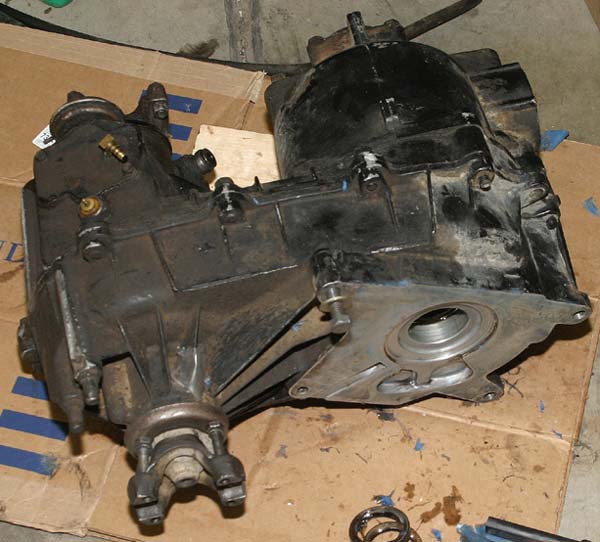
With the case now free, I slide it towards the rear of the truck. The transmission output shaft stick-out is about
6 inches! With the transfer case now completely free, I lifted it off my chest and set it down on the ground.
Removing it with the reduction (low range) attached is easier than replacing it. It is also possible to remove the
reduction unit FIRST while the case is still attached to the vehicle. This will remove a lot of weight so the
remaining part is much easier to handle.
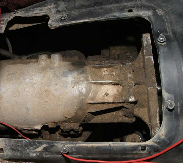
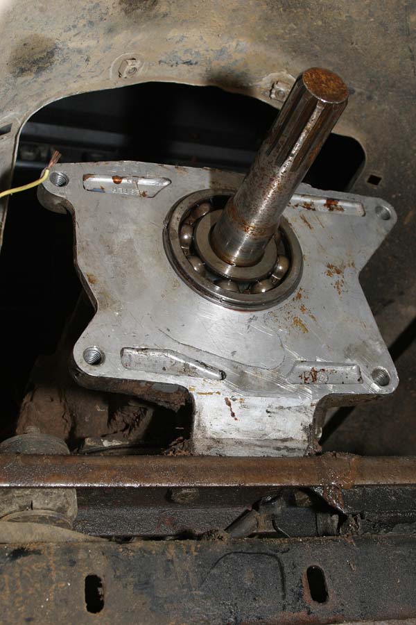
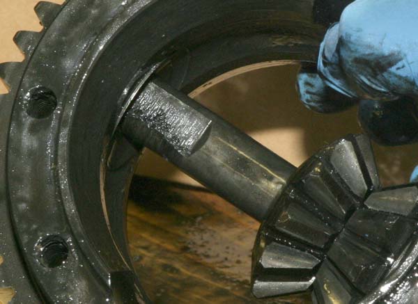
This picture shows the tail shaft adapter from the TH400
transmission and the transmission output shaft. The access
cover is the black hole above and you can see here how
convenient the access to those bolts is.
The case supposedly weighs in around 75 pounds or so. I didn't drag it onto my bathroom scale, but it
certainly is heavy. I placed wood blocks underneath it to prevent the casing from getting gouged by the
concrete floor.
If you really are just going to replace the input seals, you can do it now without opening the case. But that's no
fun.
I started opening the case by removing the E-Drive switch. The switch blocks one of the bolts holding the
case together. This is about the only dumb design flaw I can find with the unit. With the E-Drive switch out, I
removed that bolt and all the others holding the case halves together. Some of those bolts also hold the low
range reduction unit on, so I removed the reduction unit at the same time. You will notice that some of the
bolts are different lengths. It is very obvious where these go, so I did not worry about marking them or keeping
them in order. Note that two of the reduction unit bolts are smaller (1/2" head instead of 9/16"). Again, it is
obvious where they go.
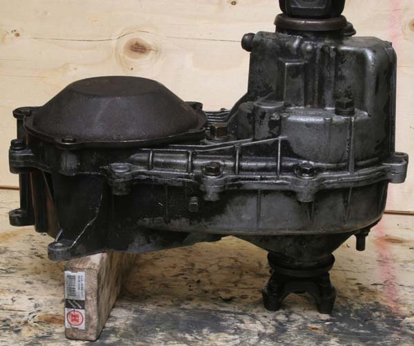
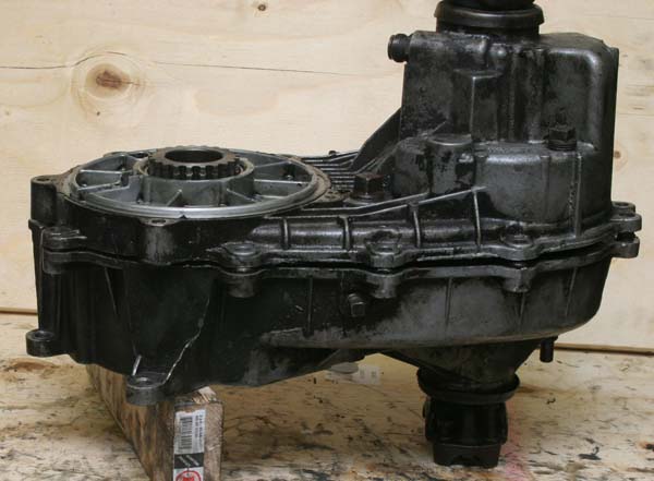
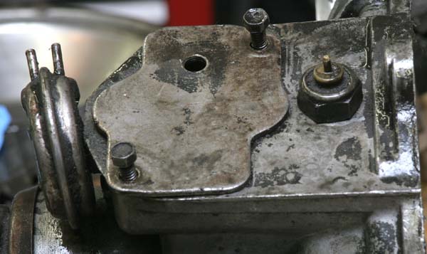
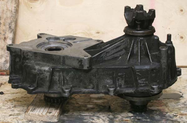
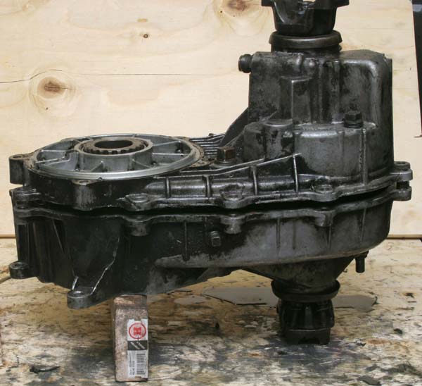
This photo shows the intact transfer case. The E-Drive switch is the yellow circle on the left side of the case
cover, just above one of the case bolts. Above the E-Drive switch is a hose barb for the vent line. The vent
line is tapped into the access cover for the E-Drive shift mechanism.
CASE DISASSEMBLY
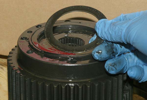
The reduction unit housing simply released from the main case. The planetary gear cage remained with the
case. There is a snap ring inside that holds it together. I removed the snap ring and the cage slid off. I
recommend using snap ring pliers. It is one of those tools that really makes life easier. They prevent lost snap
rings, gouged parts and pinched fingers.
I placed the case on a table with the transmission side facing down.
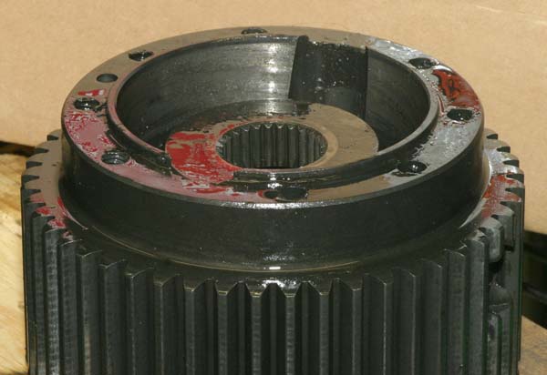
This case does not have a reduction unit so it has a cover instead.
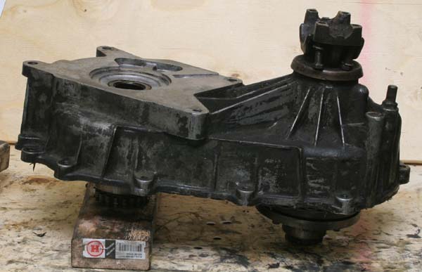
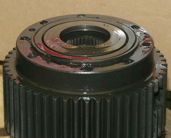
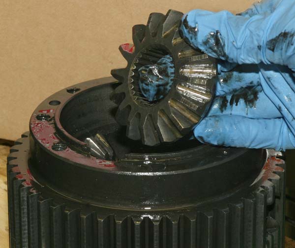
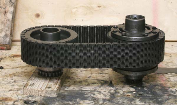
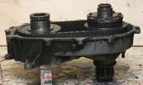
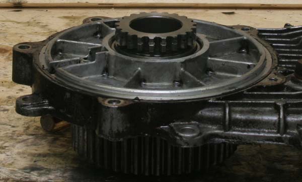
Here is the case without the reduction unit (or cover). You can see the gear where the snap ring was removed
to release the output shaft coupler (no low range) or the planetary gear set (low range)
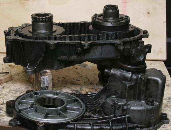
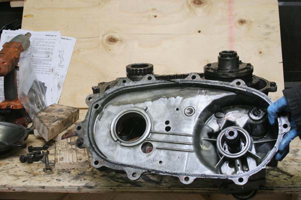
I then lifted the cover up off the case. (The TSM calls the "top" part the "transfer case cover" and refers to
the half that attaches to the transmission as the "transfer case")
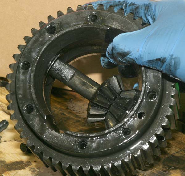
Still attached to the case is the differential (on the right), chain and drive sprocket (on the left).
Not shown, and hiding underneath the cover is a plastic thrust washer that resides on the
sprocket side of the assembly. It is plastic and rather stiff. I doubt it would handle much flexing.
I set it safely aside for re-assembly later.
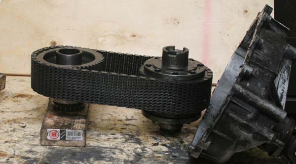
Next, I flipped over the case assembly to lift the case off of the chain/sprocket/-differential assembly.
The case is now broken down in the following major parts:
Transfer case with front pinion still attached
Transfer case cover with rear drive shaft pinion attached
Low Range Reduction unit and planetary gear set
Differential assembly
Drive Sprocket
Chain
E-DRIVE MECHANISM
I also decided to open up the E-Drive switch access plate and clean out that area, too. I removed the two
bolts that hold the access cover on.
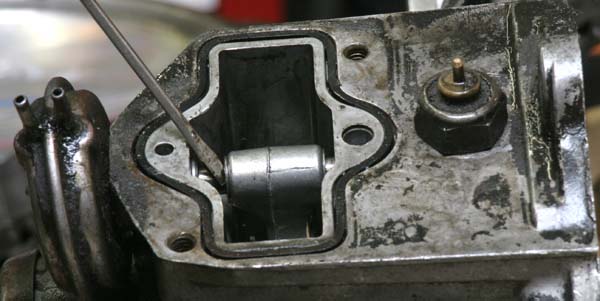
There are two springs associated with the E-Drive shift arm and fork. One is harmless and the other has a
ball bearing that can fly up at you and get lost or worse, hit you. The spring closest to the diaphragm is the
harmless one. I used a screwdriver to simply pull it out. This spring holds the E-Drive diaphragm in place and
prevents the assembly from coming out.
Note the two C-clips that hold the shift fork in place on the shift rod. I removed these easily using a small
screwdriver to pry them up. A magnet is handy here to make sure they don't go flying.
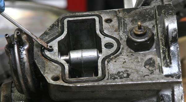
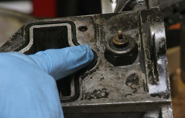
Now it was time to pull the shift rod out. There is another hole on the opposite end that is seemingly empty.
The screwdriver is pointing to the hole that contains the spring-loaded ball bearing.
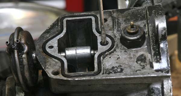
I covered this hole with my finger and slid the E-drive shift rod out of the case. The ball bearing will pop up
and I could feel it as I pulled the shift rod out.
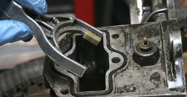
The shift fork was now free and I pulled it up and out, careful not to lose the plastic pads that attach to the
fork. I put all the E-Drive related parts in a small plastic container so they wouldn't get lost.
LIMITED SLIP DIFFERENTIAL
Next, I tackled the differential, as I had been told that a fair amount of sludge can build up in there. The TSM
makes a big deal about match-marking the differential to make sure the ends get stuck back on the same end.
I don't think that is really necessary. I removed one end, set it aside and removed the other end. I cleaned the
assembly and re-installed everything, leaving the first end alone, so there was no chance of swapping ends
incorrectly.
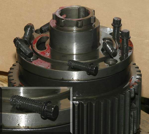
I needed a 12 point socket to remove the eight bolts on the end of the differential. Fortunately, my Sears set
actually had a nice collection of 12 point sockets. I don't know if it's a big deal, but I loosened the bolts in a
criss-cross pattern just to be safe. The differential end has a press fit on the body. A small whack with a
rubber mallet loosened the end cap and it came off easily, revealing a good amount of sludge. The cap is not
under any sort of pressure from the springs, so don't worry about it flying off.
The sludge is even all over the bolts! Yuck!
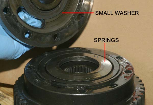
Underneath the end cap is a small washer. Mine came off with the end cap. This washer mates with the spring
plates that are still sitting in the differential unit in this photo. The springs are set in the differential so that the
outer edges are LOWER than the inner edge. This is why the small washer is on top. Yes, there is a larger
washer on the bottom of the "spring" pack.
Springs in original position
Springs removed and flipped over from original position
Now I simply removed the rest of the components as they presented themselves.
Here is the large washer removed
The friction cone being removed from the differential housing
The sides of the friction cone are rather rough and may have sharp burrs. Mine did.
All that is left is the spider gear
The spider gear just lifts out
The splines in the friction cone and the spider gear SHOULD have the same wear patterns. One of mine did
not. I purchased another QT to cannibalize and was able to find another good matching set of spider gear and
cone.
Here is the differential with both cones and ends removed. Note the hole at the end of the cross pin on the
right side. There is a solid lock pin inside that hole which locks the cross pin in place. The lock pin itself is
locked in when you re-assemble the differential and bolt both end caps on. My lock pin simply fell out. The
TSM says it's OK to drive the pin out if you need to.
Here you can see excessive wear on the cross pin. I replaced this cross pin and one of the thrust washers
from my donor unit. You can see one of the thrust washers in this photo on the upper left side, opposite the
gears.
I sprayed everything down with WD-40 and wiped the crud off with paper towels. I re-assembled the unit,
paying particular attention to the direction of the "springs" and the correct placement of the small and large
washer. BEFORE tightening the bolts on the end of the differential, I slid the differential onto one of the output
shafts to align the splines of the cone and spider gears together. If they are not aligned, you will have trouble
re-assembling the entire unit. I tightened the 12 point bolts in a criss cross pattern, even through the TSM
doesn't say to. The differential was ready to be re-installed.
E-DRIVE SHIFT FORK INSTALLATION
I previously removed the E-Drive shift fork and re-installed it after I set the gear/chain assembly in the case.
Of course, I proceeded to lose a shift fork pad inside and had to remove the gear/chain assembly to get it
back out. Don't do what I did. Re-install the shift fork assembly before installing the gear/chain assembly.
I placed the plastic pads back onto the shift fork and carefully inserted the shift fork so that it mated with the
shift collar. The shift fork should have the long part towards the rear of the case.
Next, I put a new O-ring (included in the seal kit) on the E-Drive vacuum motor shaft collar and slid it into the
case and through the shift fork.. Before the shift rod got to the ball bearing hole, I inserted the spring and the
ball bearing on top of the spring. I used a small screw driver to push the bearing down and slid the shift rod on
top of the bearing. I removed the screwdriver and slid the shift rod the rest of the way in.
I re-installed the locking spring that keeps the shift motor in place. Slide the fork towards the vacuum motor.
This will aid in case re-assembly. After fitting the new gasket into the groove, I replaced the access panel.
I didn't replace the E-Drive switch indicator because I still needed to put the case back together and insert
the case bolts.
TRANSFER CASE ASSEMBLY
Following the TSM, I placed the drive sprocket on a 3/4" thick block of wood next to the differential so that
the gears were level. I wrapped the chain around the gears and spread the gears apart to take up chain slack.
Now it was a simple matter of sliding the case on top of the gears
I carefully flipped the assembly over and rested the flat transmission mating surface on a 2x4 block of wood.
I slid the rubber case seal into the groove on the cover next.
On the left side of the cover, you can see an indentation and a notch on opposite sides of the hole for the drive
sprocket. This is where the plastic thrust washer goes. It is indexed for the notch. Use some QT fluid
to secure the washer to the cover while you install the cover.
I installed the cover simply by sliding it onto the case assembly. You may have to rotate the rear output shaft
to get the e-drive assembly to interlock correctly. At this point I installed a few case bolts finger tight to keep
everything together.
Re-installing the low range reduction unit was an interesting affair. I foolishly thought it would simply slide back
on, since it so nicely slid off when I removed it. Because you are dealing with a planetary gear set, they have
to mesh just perfectly. I was able to rotate the planetary gears individually in order to allow them to mesh with
the reduction unit. It dropped on perfectly. Except for the last quarter inch. It wouldn't budge. I removed the
reduction unit and immediately saw why. Inside the reduction unit at the bottom (as you look down into it) is a
flat gear that turns independent of the rest of the gears. Seeing that I needed to turn the main shaft in order to
turn that gear, I removed the PTO cover.
I again tried to install the reduction unit and of course AFTER I removed the PTO cover, the unit dropped all
the way on and fit correctly the first time. There was a gasket on the PTO cover. There was no replacement
gasket with my seal kit, so I re-sealed it with gasket sealer.
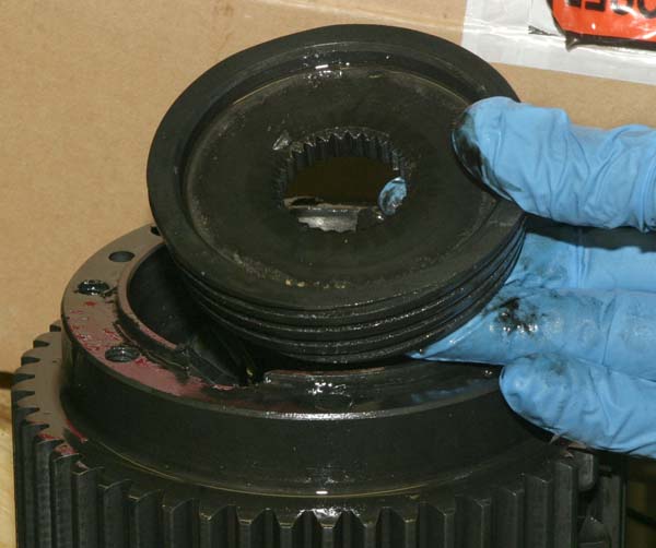
OUTPUT SHAFT COUPLER
If you do not have a reduction unit, you will have an output shaft coupler.
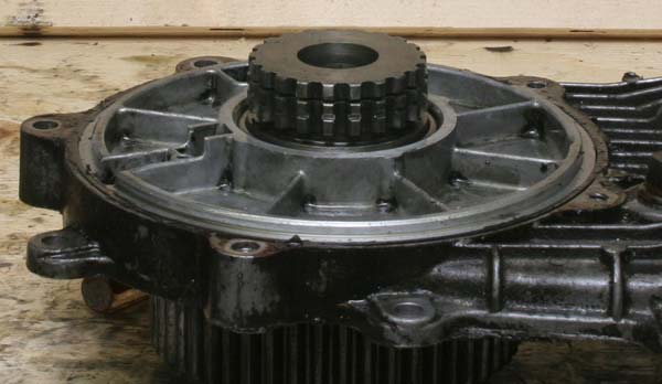
The sprocket gear protrudes like this.
Place the output shaft gear on top of the drive sprocket. Line up the gears.
Note the snap ring groove in the sprocket drive gear.
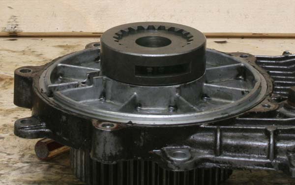
Place the coupler (with the snap ring inside!) on top and slide it down so that it mates completely
with the sprocket gear. The snap ring should set into the groove. Install the cover now to protect the assembly.
OUTPUT SHAFT SEALS
Oh, the whole reason for this was to replace the front shaft seals! That's right!
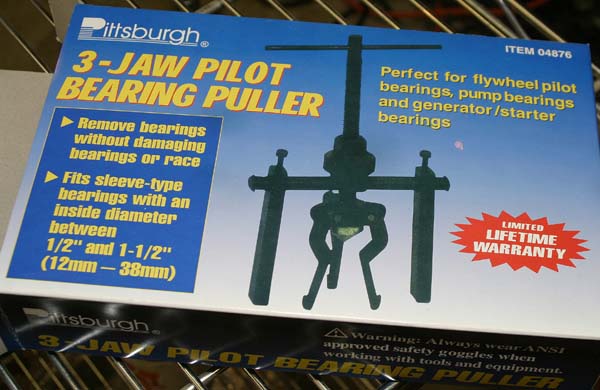
I used a Harbor Freight Seal/Bearing puller for the job. It worked great. I simply set the jaws for the correct
size and turned the big nut to pull the seals straight out. It did mangle the seals, but they're being replaced, so it
was no big deal.
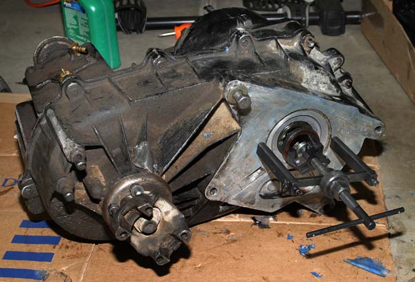
Here's the bearing/seal puller set up. I was originally worried about gouging the mating surface, but the seals
come out rather effortlessly, so it was not an issue.
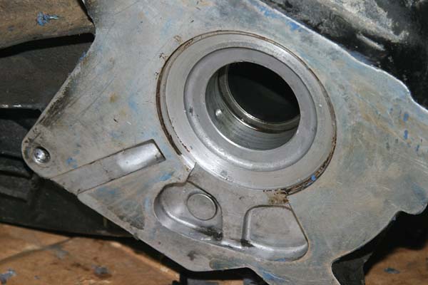
You can see the faint lines indicating where the bearings should go.
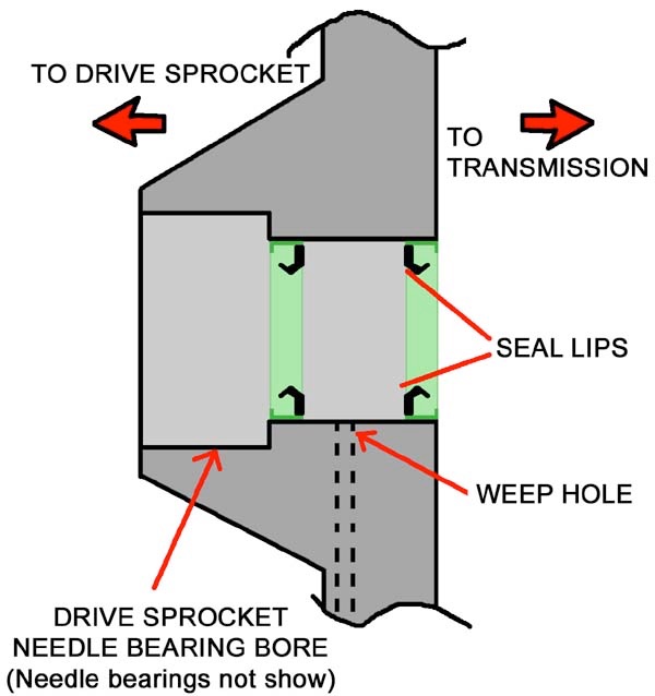
Notice the weep hole in the middle of the two seals.
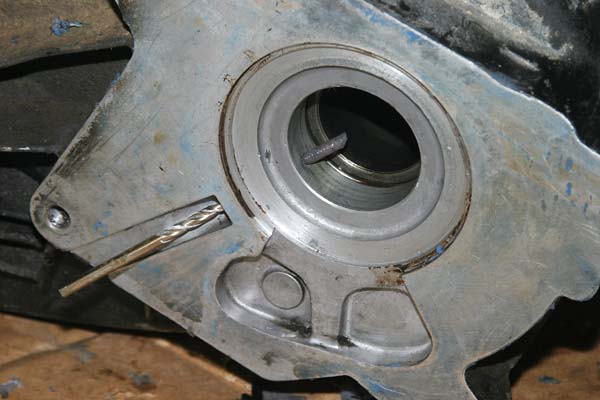
If you seal up your QT with too much sealer, this can happen. Oops.
Use a drill bit to push out the old sealant so the weep hole is clean.
The weep hole allows for inspection and verification of the seals' integrity without removing the transfer case.
If you notice fluid coming from this weep hole (a small slit at the bottom of the transfer case/transmission
mating point), it indicates that one or both of the seals have failed. Obviously, red fluid would indicate that the
transmission side seal has failed.
You can use a bearing/seal driver to reinstall the seals. The TSM goes into a big deal about using special tools
for it. I didn't have access to those tools and the old seals had left their mark, so I knew where they were to
go. Besides, it was rather obvious. They go on both sides of the weep hole, and don't block the weep hole.
Duh. I found out in the end that they sit flush with the outer surfaces.
You can get a specialized seal/bearing driver kit, but I didn't want to spring for another $16 when a big ol'
socket would do just fine. Well, problem was I didn't have any big ol' sockets that were big enough. The seal
bore is about one inch in diameter. Also, since I had to drive the first seal in rather deep, I didn't want to risk
scoring the aluminum bore. I took my seal with me to Ace Hardware and found a plastic PVC end plug that
was slightly smaller than the outside diameter of the seal. For fifty cents, I had my seal driver. If you're worried
about breaking it, buy two of them, one for each seal.
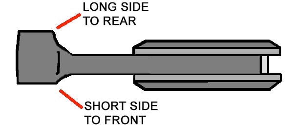
The TSM has no diagram of how to install the seals. They simply say to point the lips of the seal towards the
fluid side. That's not real helpful in my opinion, as it's hard to tell which way the seal lips are pointing.
From another service manual, I drew this diagram:
I drove both seals in from the "outside" of the case. I suppose you "could" drive the inner seal in from the
other side, but I didn't try it. It might not work, as there is a needle bearing cup on that side.
The inner seal goes in just past the weep hole. It's not that difficult to do. I used small taps on the hammer to
move it in small increments and made sure that it was going in straight. The outer seal went in just fine and I
found that by driving it flush with the mating surface, it lined up great. The weep hole was still visible and not
blocked.
RE-INSTALLATION
With the case put back together, it was time to re-attach the case to the transmission.
I removed the reduction unit for the installation and then torqued the case bolts to spec. I screwed in and
tightened the E-drive switch. Next, I installed the transmission/transfer case gasket on the transmission. I
lubricated the output shaft so it didn't damage the seals. With the reduction unit removed, I was able to bench
press the case into position and gently slide it onto the output shaft. The TSM says to install some long bolts
as guide pins, but I found it wasn't necessary. I bolted up the case to the transmission and reconnected the
drive shafts, E-drive switch wire, speedometer cable, vacuum lines and low range lever.
Installing the reduction unit while the case is connected to the truck was pleasantly easy to do. Again, you have
to make sure that the planetary gears are aligned just right. All the connecting bolts are easy to get to and don't
require too much twisting to get to.
The label on the QT fluid bottle says to shake well. To refill the case, I removed the low range fill plug first. I
filled the reduction unit until fluid started coming back out and re-inserted and tightened the plug. Next, I
removed the main case fill plug and did the same. Both of the fill holes are all vertically oriented, so you need
either a funnel with a hose on the end or a squeeze bottle of sorts. I used a squeeze bottle.
Now my QT is reconditioned and ready to hit the trails.
WRAP UP:
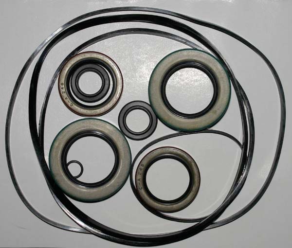
Here is what you get with the QT seal kit from BJ's Offroad. They offer fast shipping and fair prices. Not shown,
but included, is the tranmission/transfer case mating gasket.
Note that I did not replace the pinion seals, as the case wasn't leaking there.
If your QT unit is leaking or making noises or vibrations that it should not, you now have no excuse
for not diving in and repairing your transfer case.
Take me back to the Big Scary Jeep homepage!
Removal, disassembly, assembly and re-installation of a
Quadra-Trac transfer case in an SJ series truck.
