M715 Front Disc Brake Conversion Kit Installation

Follow along as I show you how I installed my front disc brakes using the conversion kit from Helitool. If you are interested in this conversion, call Ray and check on availability. He does batches and may or may not have them in stock. Once you receive the kit, you will realize it was worth the wait.
I ordered my kit and it arrived quickly and extremely well packaged. Ray knows how to pack heavy items so they are well protected and do not shift in transit. I received three boxes. The hub/rotor assemblies each came in their own box and the brackets, hoses and hardware filled the third box. The brackets are well made and extremely heavy duty.
As their website says, you need to purchase locally a set of 1994 F-350 one ton calipers and (of course) pads. I purchased the softest pads available, which were semi-metallic. You will have to re-route your brake lines one way or another (More details below). I purchased a short piece of brake line once I decided on a new mounting location for the hoses. The kit contains everything else you will need.
If you don’t already have them, you will also need the following tools:
STANDARD 2 1/2” hub socket (NOT the one with rounded corners for the “special” Ford hub nut) You can get this at Napa.
Appropriate adapter or ratchet for the hub socket. My hub socket was 3/4” drive. I had to buy an adapter since I have no 3/4” ratchets.
While you are at it, plan on possibly replacing your inner and outer bearings and DEFINITELY plan on replacing the inner seal. It is a press fit item and I found it very difficult to remove it without damaging the seal. I saved one, but not the other. Since I knew my hubs had been rebuilt in the past 5 years, I knew the seal was OK. If you have any doubts, replace the seal. Unfortunately, the seal is $53 as of 2007. Napa did not have any in stock and I had to order mine in. Only took about 4 days.
Clean and inspect your bearings and replace them if they look suspect. If Ray sends you a NOS hub, the race will already be installed. Check first, before you order a new race. My bearings were fine.
Now that I had my tools and parts lined up, it was time to get started.
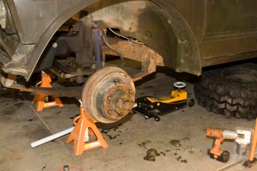
After jacking up the front axle, I removed the wheel.
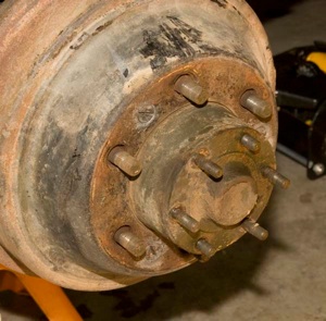
Then I removed the nuts holding the hub shackle attachment point. Pry off the drive flange (manual says to use a rawhide hammer). I found that a flathead screwdriver and a small hammer works well. Once you have a small gap, prying with two screwdrivers on opposite sides will persuade the flange to come off evenly without binding on the studs.
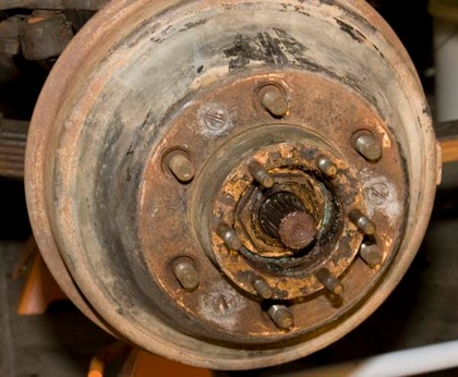
Next I removed the three screws holding the drum to the hub.
Wiggling the drum fore and aft is the best way to get it to come off. You can also turn the starwheel adjuster to collapse the shoes, but I found it wasn’t required. Also, the jackstands are usually right in the way of getting to the starwheel adjuster.
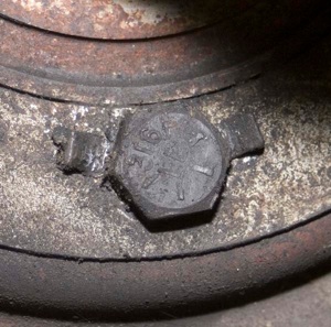
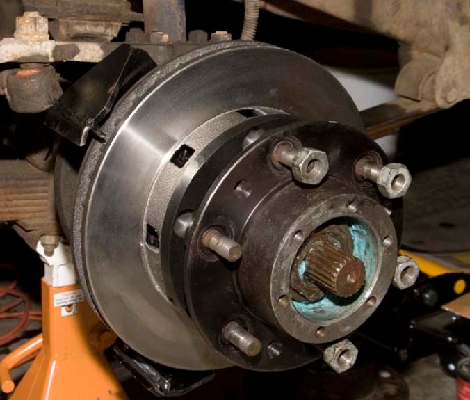
Now you’re staring at a big nut. Use your hub socket to remove the first locknut.
Next to come out is the lock washer. Again, two screwdrivers on opposite sides make quick work of this task.
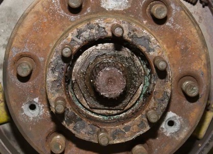
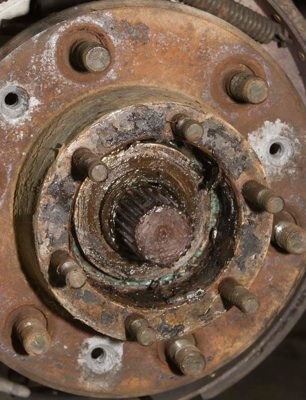
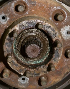
Now remove the inner nut. This is the one that actually applies the pressure to the outer bearing.
Behind this nut is a flat washer. You can remove it, but it will also come out when you slide the hub assembly off the spindle.
Be careful, as the hub is rather heavy for its size. The inner bearing and washer (if you haven’t removed it) will want to fall out. Catch it so it doesn’t pick up all the dirt on your garage floor.
With the hub assembly removed, you can now remove the 5 bolts holding the drum brake backing plate and spindle to the knuckle. There may or may not be a pressed metal “ring” with locking tabs around the bolts. Simply push the tabs away from the bolt head and remove the bolts. Lock washers are included in the kit, so this “tab ring” does not need to be re-used.
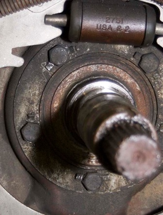
The spindle may or may not want to come loose. It can’t move too much, as the axle shaft sort of holds it up. Remove the drum brake plate and set it aside. Someone might want it, and the wheel cylinders and shoes are interchangeable with the rears.
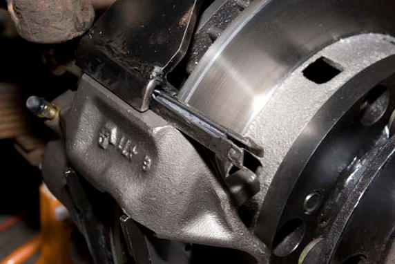
Grab the correct caliper bracket. You want the one that will point the caliper towards the FRONT of the truck, regardless of which side of the truck you are working on. This orientation is opposite of what is shown in the manual because the manual shows a Dodge application.
The photo on the right is of the DRIVER’S side. All photos are of the DRIVER’S side, unless otherwise noted.
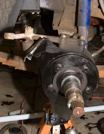
Ray confirmed that the Dodge and M715 mounting is opposite. It will look like the bracket or caliper comes close to the steering arms, but there is plenty of space.
The rotor will also be quite close to the bracket.
Insert and tighten the 5 bolt/washers to secure the bracket and torque to spec. The spindle goes on the knuckle first, then the caliper bracket.
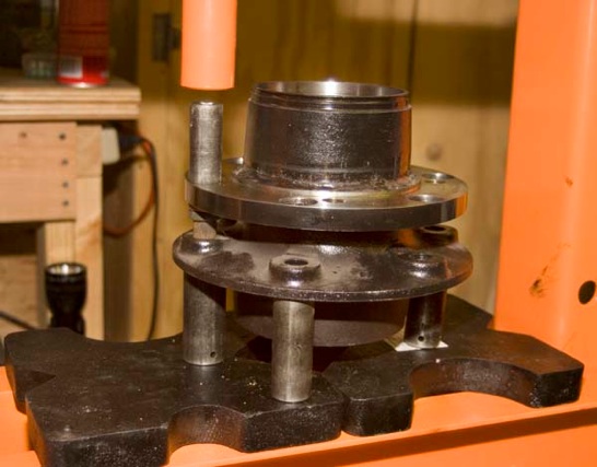
You will now need to press out your old wheel studs from your old hub. You can do this with a hydraulic press or stick a lug nut on the end of the stud and pound it out with a hammer like I did.
Take your new modified hub and remove the rotor from the hub. Press your old studs into the modified hub. You will need to press the studs ALL THE WAY in so that they rest squarely on the back surface of the hub. If you see any space between the back of the hub and the “head” of the stud, it is not seated all the way in and the wheel will be difficult or impossible to mount.
I “made” my studs go into the wheel and then torqued the wheel nuts to seat the studs. This worked fine, but I did have to have the threads cleaned up by a machinist. If you happen to have a 5/8” 18 TPI die set, great. I didn’t, so I had someone else clean them up for me.
If you press your studs in with a hydraulic press like I did, make sure your base is NOT made out of sintered metal. The Harbor Freight press I bought had sintered metal base plates which shattered on me. If I had known what type of metal they were, I NEVER would have used them. Sintered metal is just like cinder block. And just like cinder block, when it cracks, it fails instantly, giving you no “running time”, as it is known. (Concrete with iron re-bar, for example, has “running time”. Quite literally, it refers to the time you have to run out of the building and/or away from the structure before total collapse)
DON”T USE THESE SINTERED
METAL PLATES!!!!!
OK, back to our disc brakes....
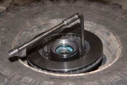
With your studs seated nice and squarely, it’s time to reinstall the rotor on the hub. Lay one of your wheels (with a tire mounted on it) flat on the ground. Insert the hub onto the wheel, with the studs in the mounting holes. Set the rotor on the machined rotor mounting flange. Insert the cap screws by hand first. Do all 4 this way before you tighten them down. It is easier to get that last bolt started this way! Tighten and torque to spec.
What? You don’t have a 1/2” allen hex socket??? No worry, you can use the an Allen wrench “key”. Insert the key the only way it will work, with the long end in the bolt head. Attach a 1/2” socket to the other end. Insert a ratchet extension into the other end of the socket and now you can tighten the bolt.
With the rotor securely mounted to your hub, grease and insert your inner bearing into the back side of the hub. Drive the inner grease seal into the hub which captures your inner bearing. Throw some more grease into the bearing cavity. You don’t want to have to pull of the hub again for a long time! Put some grease on your spindle and carefully slide the hub onto the spindle. The inner bearing is sort of just flopping around in there and it may take several tries to get it to slide correctly onto the spindle. It’s a close tolerance fit.
With the hub on, insert the outer bearing. Install the flat washer, next. Tighten by hand the inner nut. My manual states to tighten the nut to 50 ft-lbs and back off 1/4 turn. Rotate the nut so that you can install the locking flange and install the outer nut. Torque the outer nut to 50 ft-lbs. Your new modified hub is now installed.
Clean your hands (or put on new gloves) and load your caliper. My pads from Napa were labeled I and O, for inner and Outer. For the calipers themselves, you want to REVERSE the sides that are labeled on your caliper. Thus, use the LEFT caliper on the RIGHT side of the truck. Still confused? In the end, you want the bleeder screw and hose connection at the top of the caliper. Insert the pads. You may have to compress the piston side with a C-clamp in order to spread out the pads to fit on the rotor.
Without the keepers, the caliper will just sort of hang there and want to fall out. It is different than GM or Full Size Jeep calipers which use caliper bolts to hold them to the bracket.
Install the keepers with the “nubs” facing AWAY from the caliper. Drive them in until you hear the “click” the nub on the inside makes when it reaches the other side. Hold onto the caliper until you insert the second nub, as the caliper can still fall off the bracket.
The instructions say to check the caliper clearance to the knuckle. I did not notice any interference with my remanufactured calipers from Napa.
After installing the caliper keepers, install the Z-spring as shown in the photo on the left.
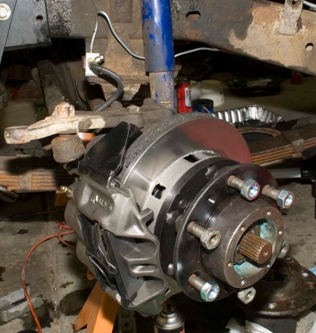
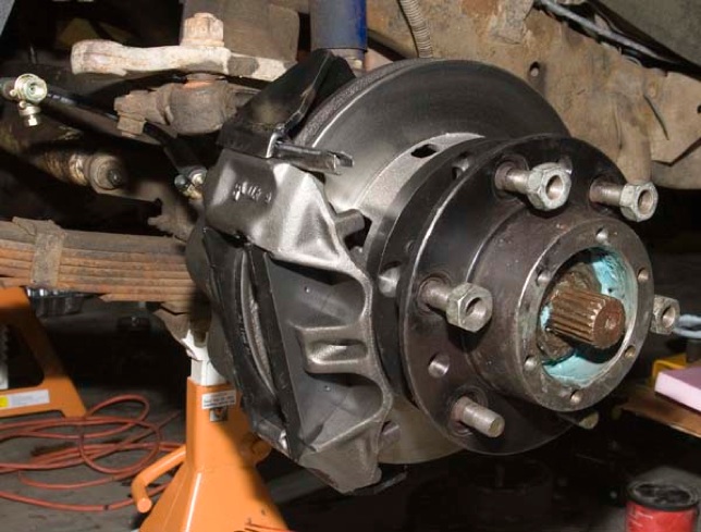
Here is the completed setup. Don’t forget to re-install your hub flange and your lifting shackles!
Once the brakes lines are all connected, plumb them to your favorite disc/drum master cylinder, bleed the brakes, put your wheels back on and go for a road test.
Per the recommendation of Ray (the guy who makes the kit), I used a master cylinder from a 1980 Chevy 1 ton pickup. The NAPA part # is SS 4739017. It has a 1 5/16” bore and bolts right up to the FSJ dual diaphragm brake booster.
I originally tried the single diaphragm booster from an FSJ, but it was either bad or not powerful enough. When I compared the two, the dual diaphragm booster also had more travel. With the dual diaphragm booster, I have excellent braking power and good pedal travel. The truck stops without me having to push the pedal to the floor. When the truck stops, I still have extra travel in the pedal. I expect the braking to improve more as the pads get broken in.
The price of the kit (in 2007) was $595 plus shipping. The calipers were $53 EACH, with a core charge of $55 EACH. Yes, the core charge is more than the caliper itself.
I purchased the softest pads available, for around $30 for set.
The master cylinder was about $40, including the core charge.
Yup, total cost was about $881 plus shipping. Yup, you could buy a set of used axles for that price, but then I’d (most likely) lose the 5.87 gearing and my Detroit locker AND I’d have to get new wheels. Also, I’d lose the stock look of the running gear. So, for me, it was worth it.
The above photo shows the PASSENGER (RIGHT) side hose installed. Check your clearances by turning the steering to full lock both left and right.
The hoses install with the flat surface towards the caliper. One side has a straight machined ridge. This side faces down and contacts the caliper. The hose should point perpendicular to the rotor’s machined surface. They really only fit one way and there IS a left and right hose.
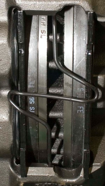
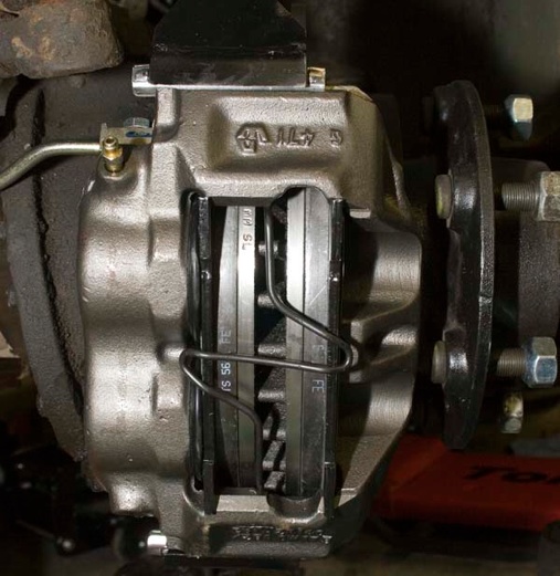
Above is the assembled caliper.
Ray had suggested running the hoses to hard lines mounted on the axle and then connecting the hard line to just one flexible hose, similar to the setup used on the rear axle. Ray stated that this would allow for more articulation of the front axle without stressing the brake hoses.
If you don’t do this, you will have to relocate the frame mounted hard lines. The brake hoses supplied are too short to reach back to the stock location.
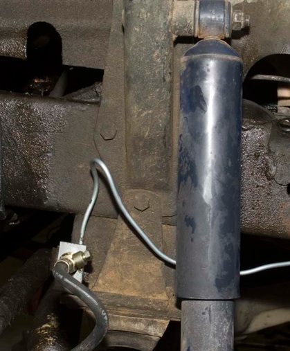
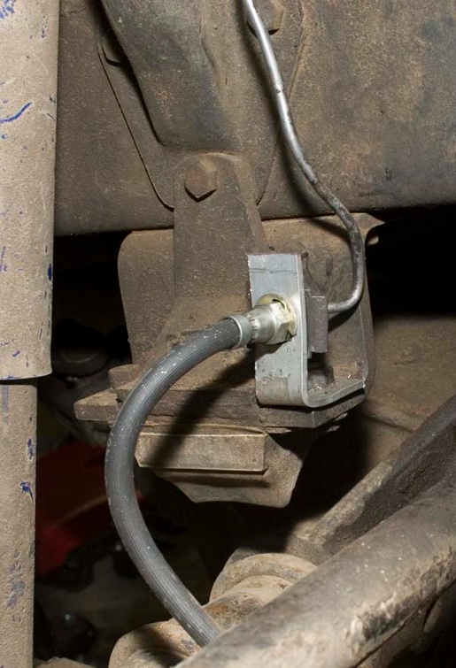
I bent up a new brake line holder and mounted it onto the top of the bump stop bolt, as shown in the following two photos. I used aluminum flat bar stock because it is easy to bend and drill through.
This is the driver’s side brake line modification. I had to purchase a new line for this side only, as the original line was too short to reach to the other side of the shock tower and bump stop mount.
This view of the PASSENGER side brake line modification shows how the bracket is bent and bolted to the bump stop. Turning the steering in both directions show that it is impossible for the hose to ever get caught under the bump stop.